
Controller design of rotational disc
January 2021 - May 2021PD PID Controller design for 2 DOF system using root locus
Overview
The report below details the process of building several controllers, such as PD and PID controllers for 2-DOF systems. The 2-DOF system consists of two circular plates connected by a flexible rod that acts as a torsional spring, as shown below in figure 1.
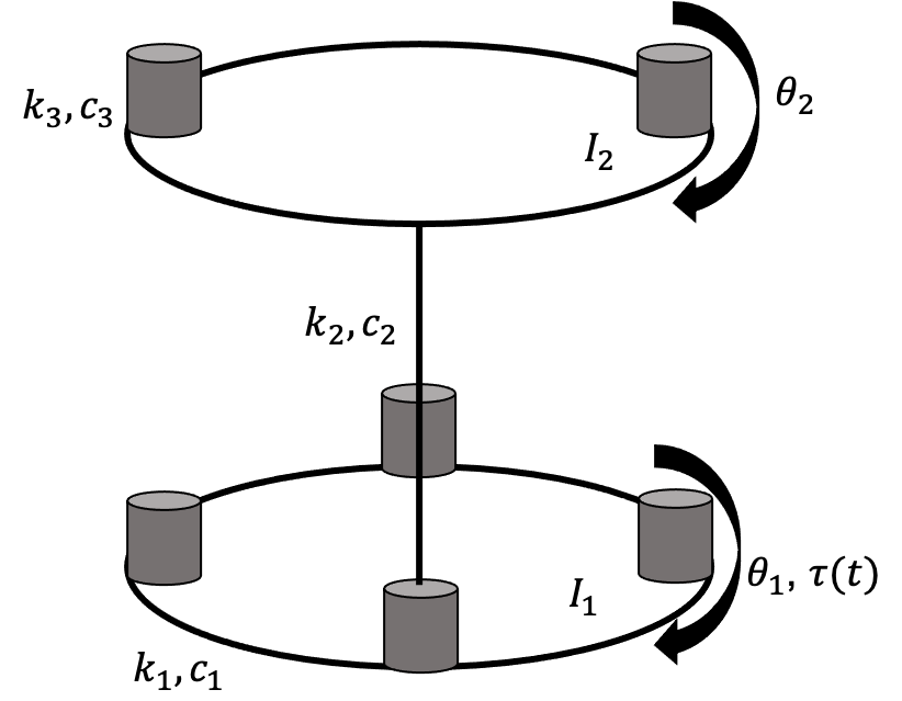
Torque τ is applied to the lower plate which moves the plate I1. The plate I1 moves an angle θ1, which is directly controlled by the controller. I1 is also connected to the plate I2 through a flexible rod. The motion in I1 causes motion in I2. This motion is captured by θ2. The objective in this report is to show various controllers for I1 and I2.
FeedBack Control Design
A controller is used to drive the system to the desired output. One of the hallmarks of a controller is using a negative feedback loop. Feedback controller means that the output of the system is fed in as an input to the controller. Negative feedback means that this feedback is subtracted from the input to give us the error. The controller is designed such that it minimizes this error to drive the system to the desired output. In a 2-DOF system controller, different controller designs are used to control different things.
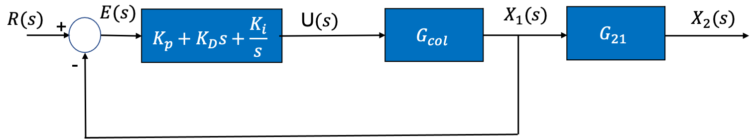
Collocated controllers are used to control the disc connected to the actuator directly. It is the most effective controller. The block diagram below shows how the Collocated controller is set up. It aims to control x1 by controlling the response of the collocated plant Gcol which is defined in equation 8. In the block diagrams, U(s) represents the control effort, X1(s) the position θ1 of directly controlled disc while X2(s) the position θ2 of the indirectly controlled disc.
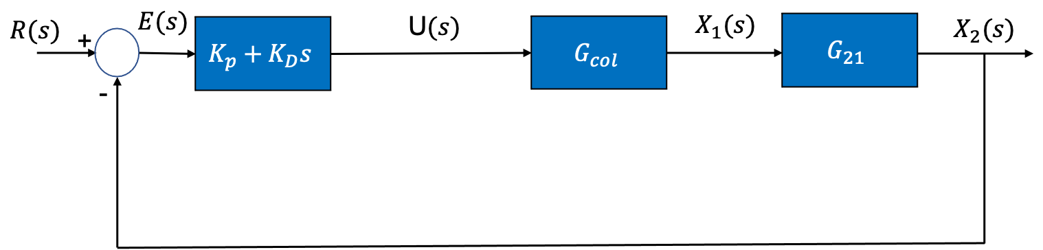
Non-Collocated Controllers are designed to control the second disk that is connected to the first disk by a flexible rod. The block diagram below shows how the Non-Collocated controller is set up. It aims to control x2 by controlling the response of the collocated plant Gncol which is defined in equation 9. Gncol = Gcol • G21 in the figure below.
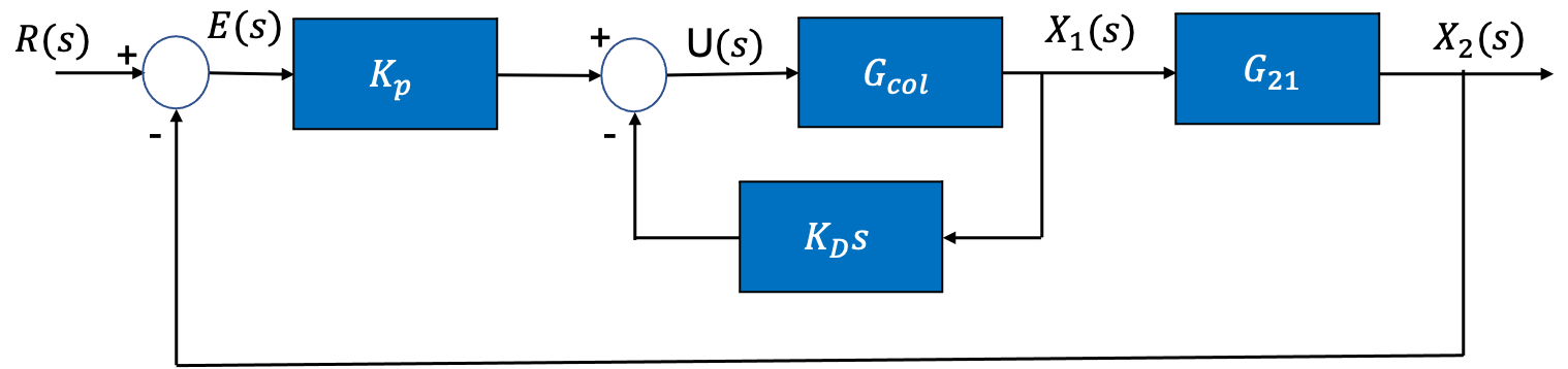
Mixed Controllers are designed to control the velocity of the collocated plant and the position of the non-collocated plant, as shown in the figure below. It takes x1 and does a feedback derivative control on that while it takes x2 and controls its position using proportional control. This is a hybrid controller meant to control both the disks.
These 3 control objected are achieved in various ways.
Design Approach
The aim was to minimize the maximum overshoot and the settling time of the response, the control effort and the steady state error. This was done through PD and PID controllers, in their cascade and velocity feedback architectures (block diagram shown for each individual controller design). These controllers were designed using sisotool. The root locus was changed to give the desired output. The figure 10 a shows root locus of the PD series controlled system. To increase the design space, the real zero was moved sufficiently. The closed loop poles shown in solid pink are moved around to give the desired results, either to reduce maximum overshoot, settling time, control effort or steady state error.
Link for report
For full report, please check this out